Hydraulic Separator Piping Diagram: Make Your Processes Cleaner
-
 2022-10-21
-

When it comes to operating processes, especially within the refinery or chemical plant, there are a number of different factors that must be taken into account. After all, these are complex machines with many interworking parts — pieces that need to function in perfect unison in order to produce the end product. In this blog post, you will learn about the importance of piping diagrams, what they are and why they’re so beneficial. You’ll also be introduced to the concept of a hydraulic separator and its role when it comes to piping diagrams and separating fluids. Lastly, we’ll explore the benefits of creating your own piping diagram for your specific separation process so you can make your processes cleaner than ever before
What is a Piping Diagram?
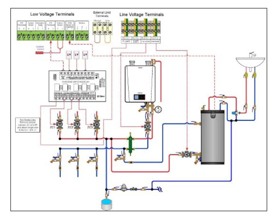
A piping diagram is a visual representation of all the piping and equipment used within the process. It’s there to help illustrate how everything is connected and where the flow of materials will go. In other words — a piping diagram will show you how the product is flowing within your machinery. Piping diagrams are created in a CAD (Computer-Aided Design) program and are typically used in the design phase of any complex process. However, they are also beneficial after the design phase as they can be used to troubleshoot and inspect the equipment when something goes wrong. A piping diagram may sound like a pretty straightforward concept, but it can actually be a pretty complex piece of design. You need to know the expected flow rate of your product, the capacities of the various pipes, and so forth.
What is a Hydraulic Separator?
Hydraulic separators are devices used for the separation of liquids and gases by means of hydrostatic pressure. Basically, it’s a way to separate heavier materials from lighter materials, such as water from natural gas. It uses the combination of pressure and gravity to separate water from natural gas. The fluid enters the separator through a pressure-controlled inlet valve, flows upward through the separator, and discharges out of one or more outlet valves. The pressure drop in the separator creates a lift in the heavier liquid that allows it to flow up the separator while the lighter gas flows downward through the outlet valves.
Why is a Piping Diagram Beneficial for a Hydraulic Separator?
As we just explored, a hydraulic separator is used to separate liquids and gases by means of hydrostatic pressure. This can be beneficial when it comes to separating heavier fluids from lighter fluids within the hydraulic process. However, what may not be so clear is how a piping diagram can help to make this process even more efficient. The first step is to understand which piping diagram is right for your equipment. In other words, you need to know what piping diagram will work best for your hydraulic separator. There are different types of piping diagrams, each with their own unique purpose. The easiest way to navigate this is to understand the concept of a topology. A topology is basically a diagram that explains how a network is connected and how the various devices are managed as a whole. In other words, it will show you how your system flows.
How to Create your Own Piping Diagram for Your Processes
As we mentioned earlier, a piping diagram can be beneficial throughout the entire process. However, if you already have a piping diagram in place and don’t wish to create a new one, that’s perfectly fine too. Should you decide to create a new piping diagram, there are a few things to keep in mind. First and foremost, before you even touch a piece of paper, you need to know how the process works. You need to understand exactly how everything comes together and what each piece of equipment does. Once you have a clear understanding of the process, you can start creating your diagram. To get started, you can choose to use one of the many programs available online or on your computer. You can also use a pen and paper. No matter which option you choose, make sure you start with the process. You need to begin with a sketch and work your way up from there.
Final Words
A Hydraulic piping diagram is a visual representation of an entire process. It’s used to show the various pieces that make up the system, how they’re connected, and what they do. A piping diagram can be beneficial for a number of reasons. It can help you understand your processes better and find ways to make them more efficient. It can also be beneficial when it comes to troubleshooting and inspecting your equipment when something goes wrong. When it comes to operating processes, especially within the refinery or chemical plant, there are a number of different factors that must be taken into account. After all, these are complex machines with many interworking parts — pieces that need to function in perfect unison in order to produce the end product.


